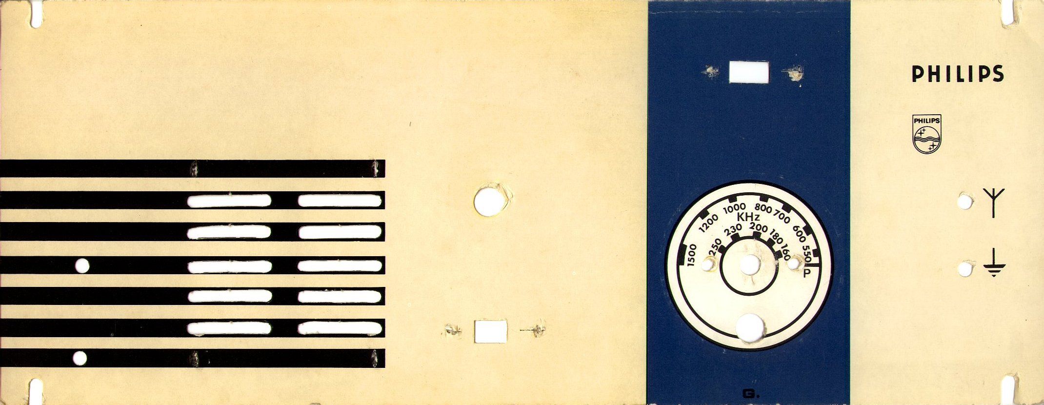
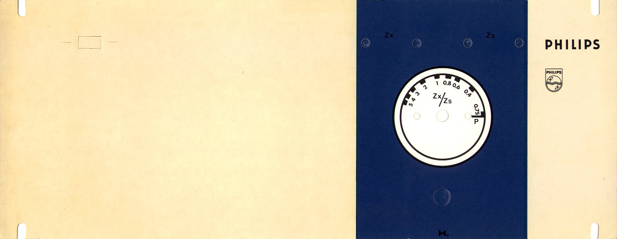
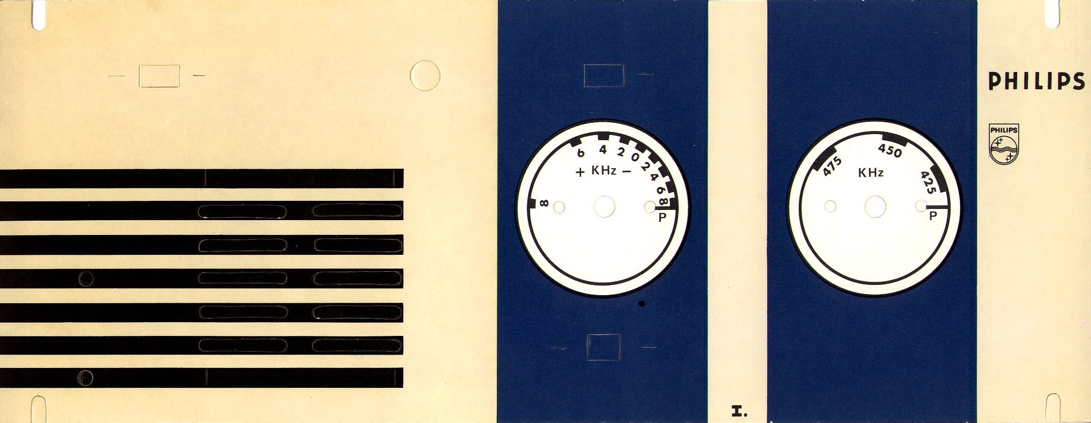
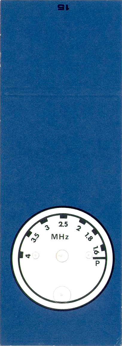
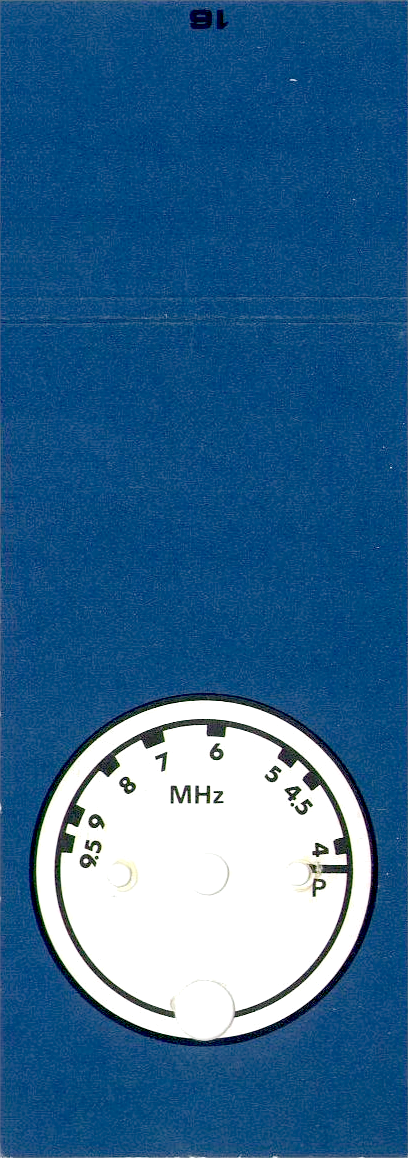
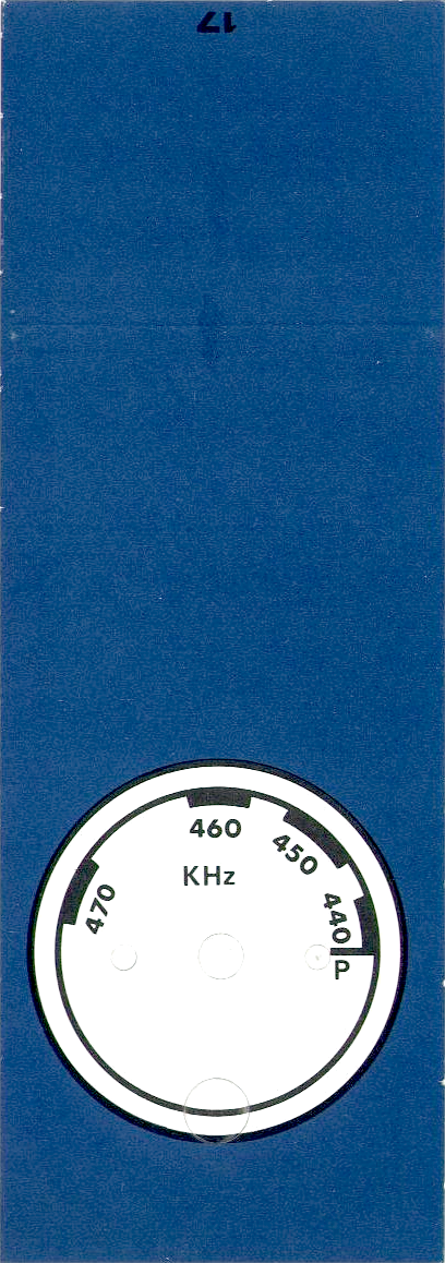
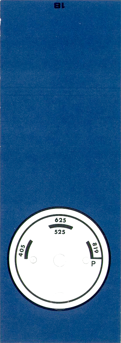
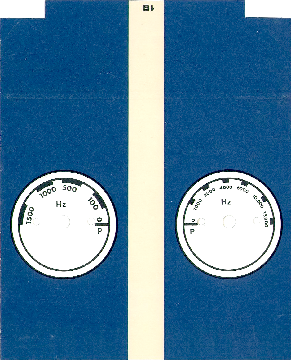
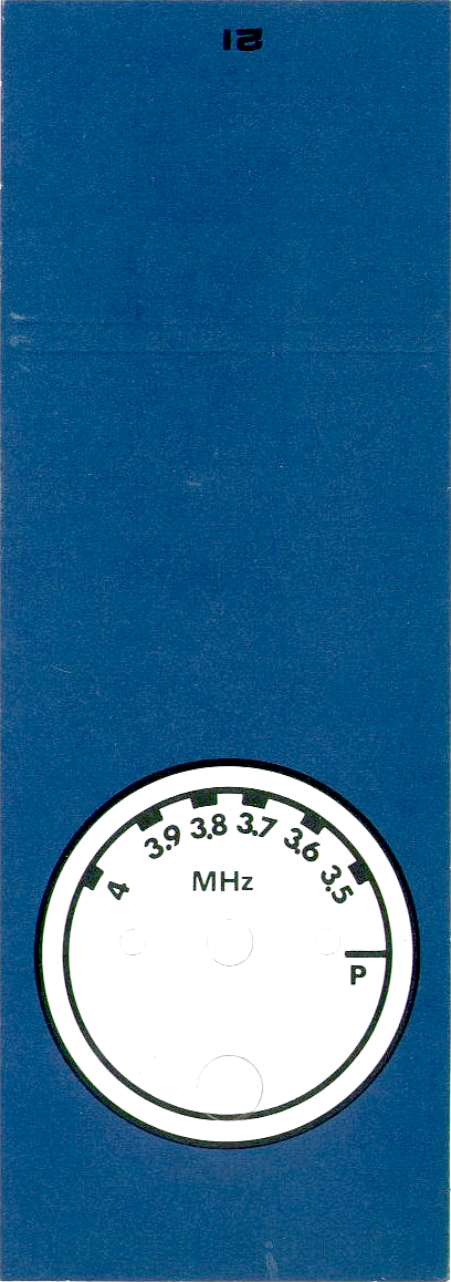
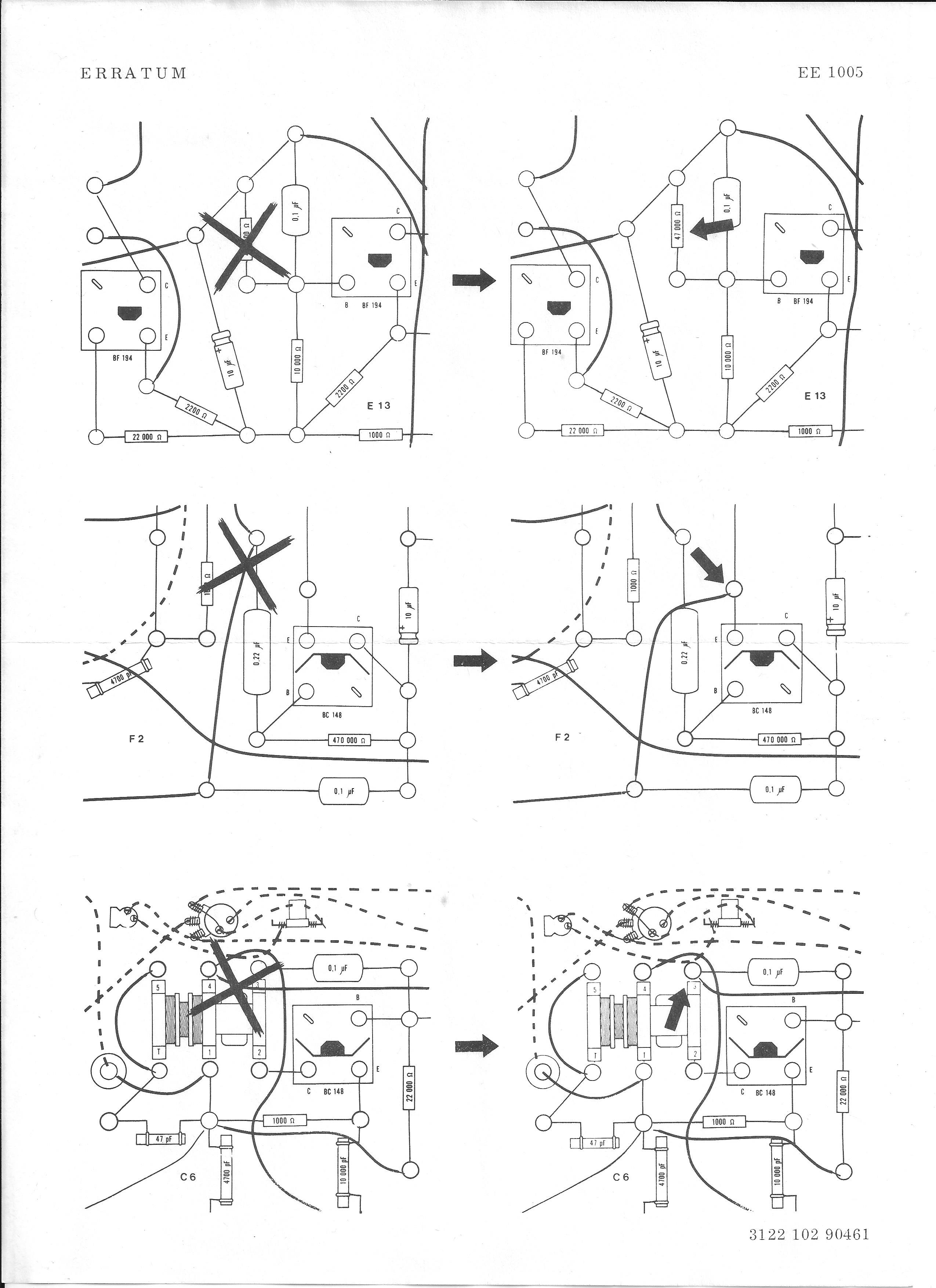
(from a kit with the 1968 version of the manual).
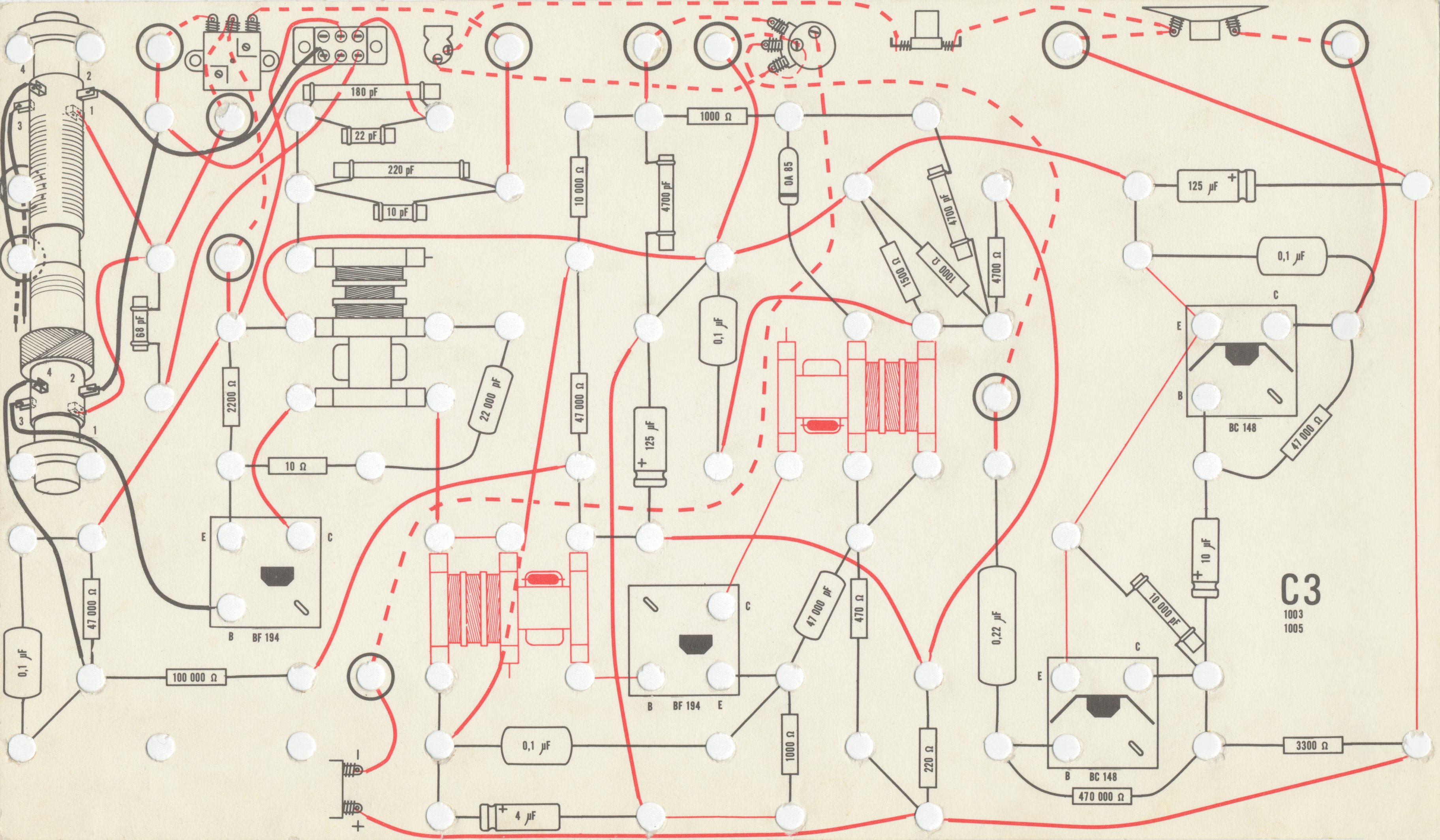
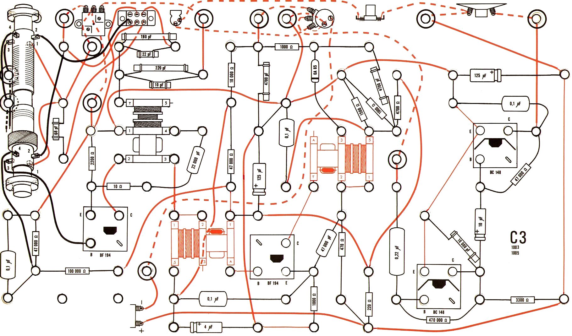
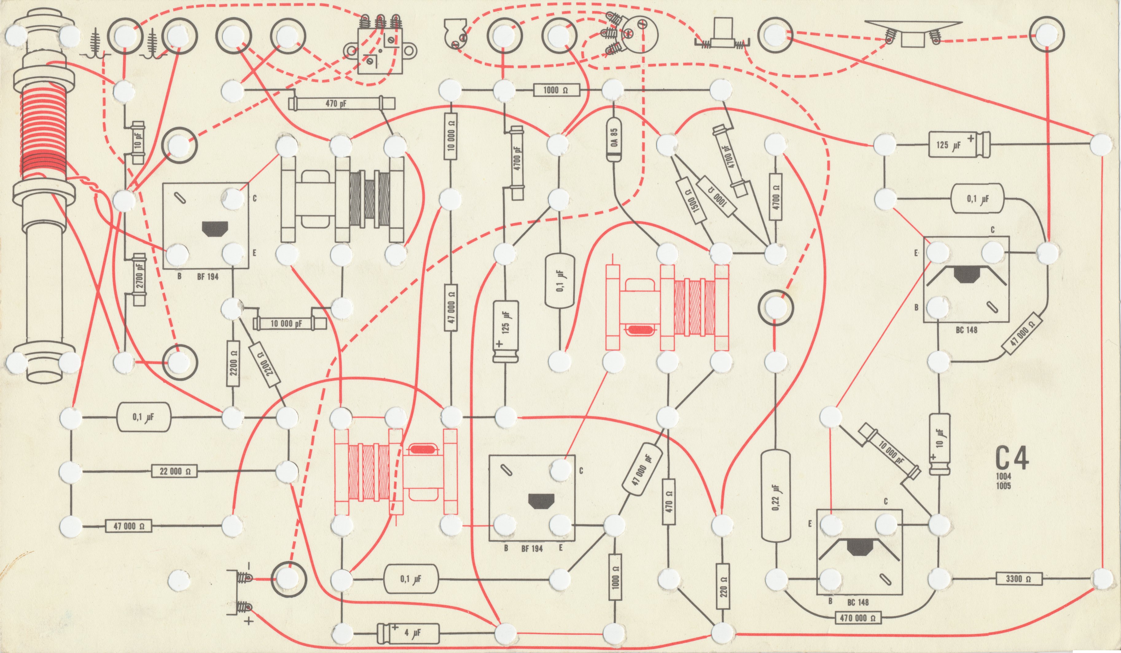
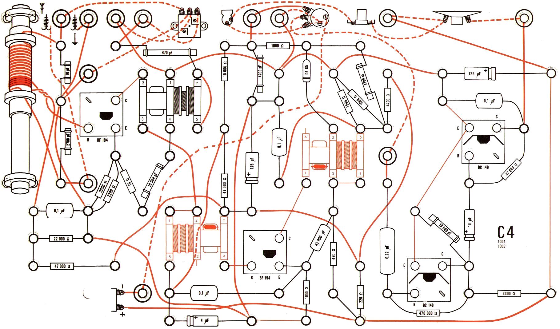
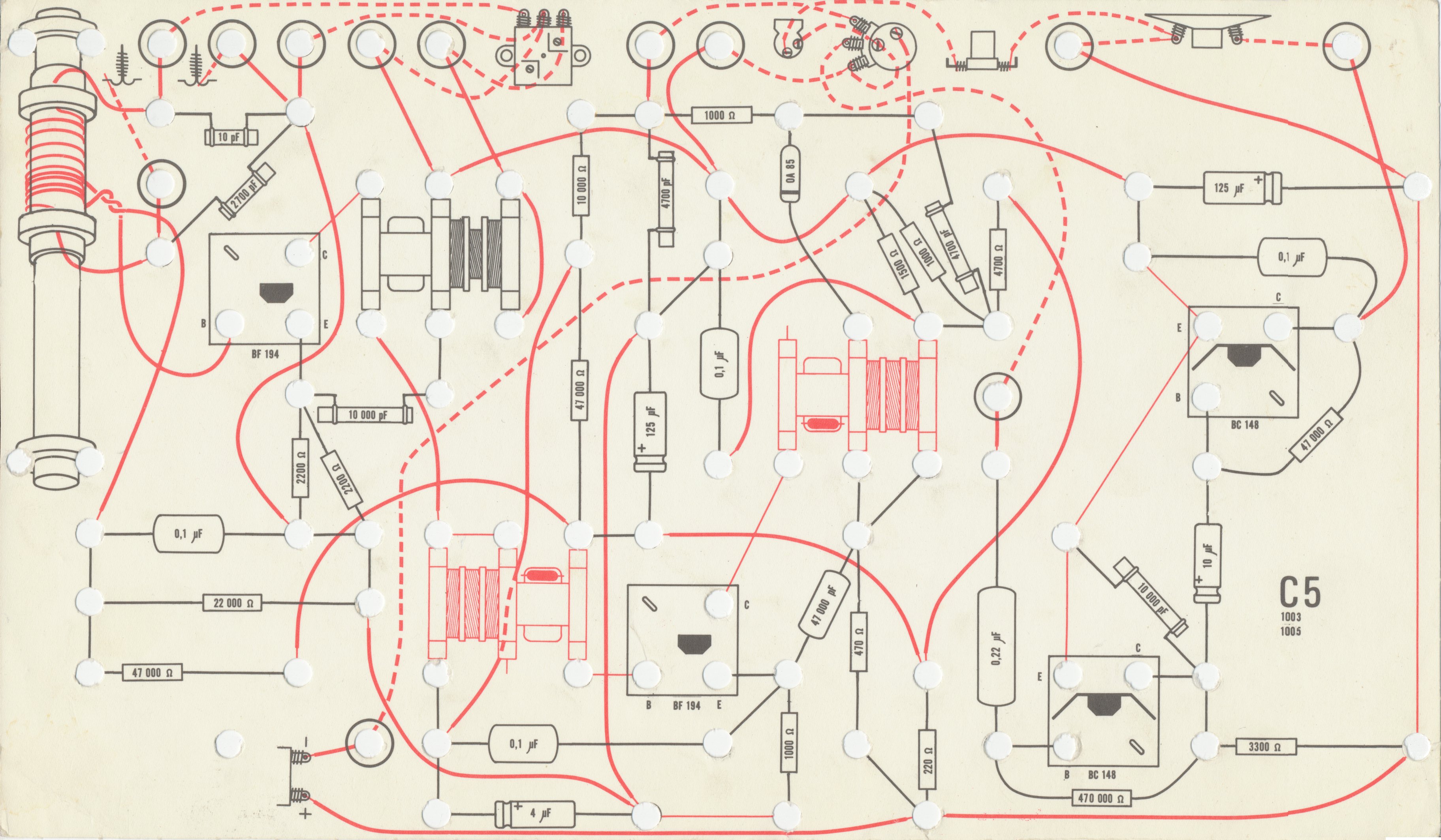
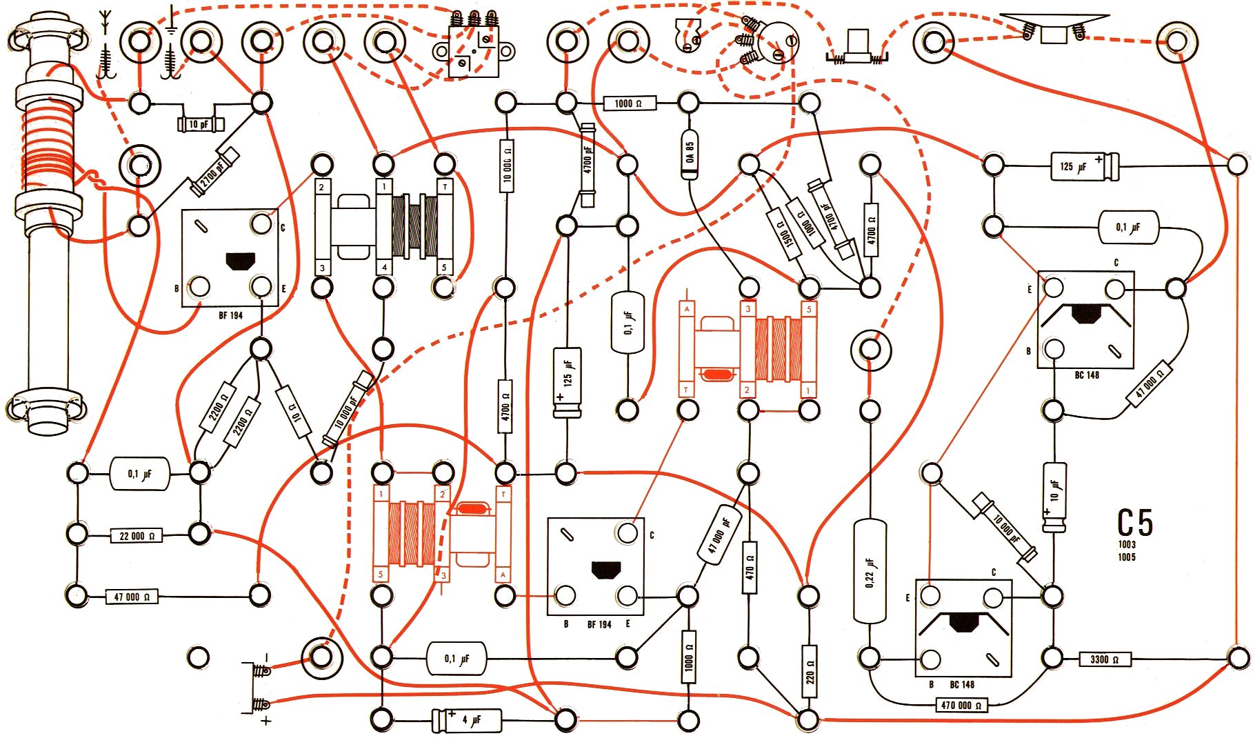
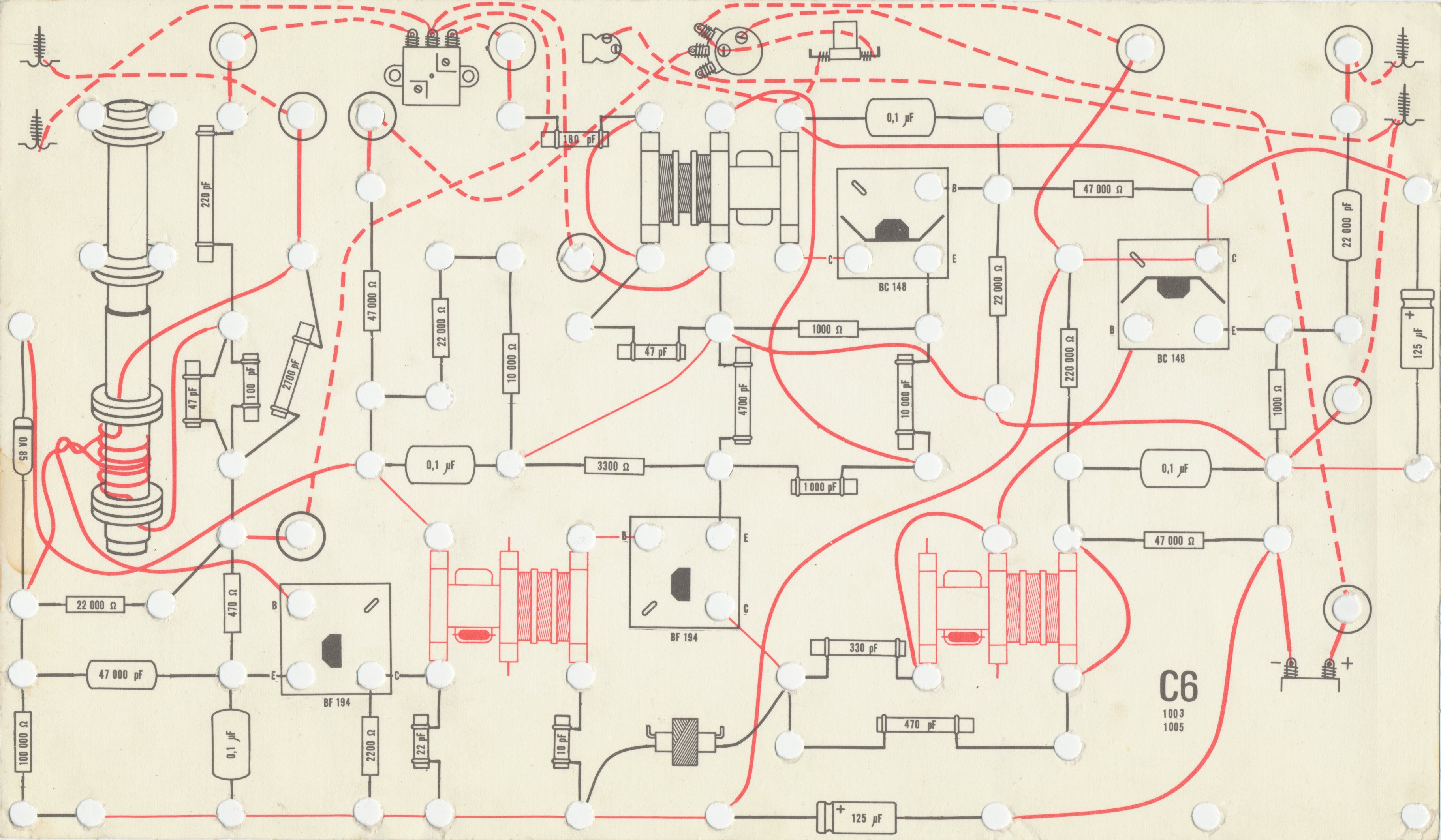
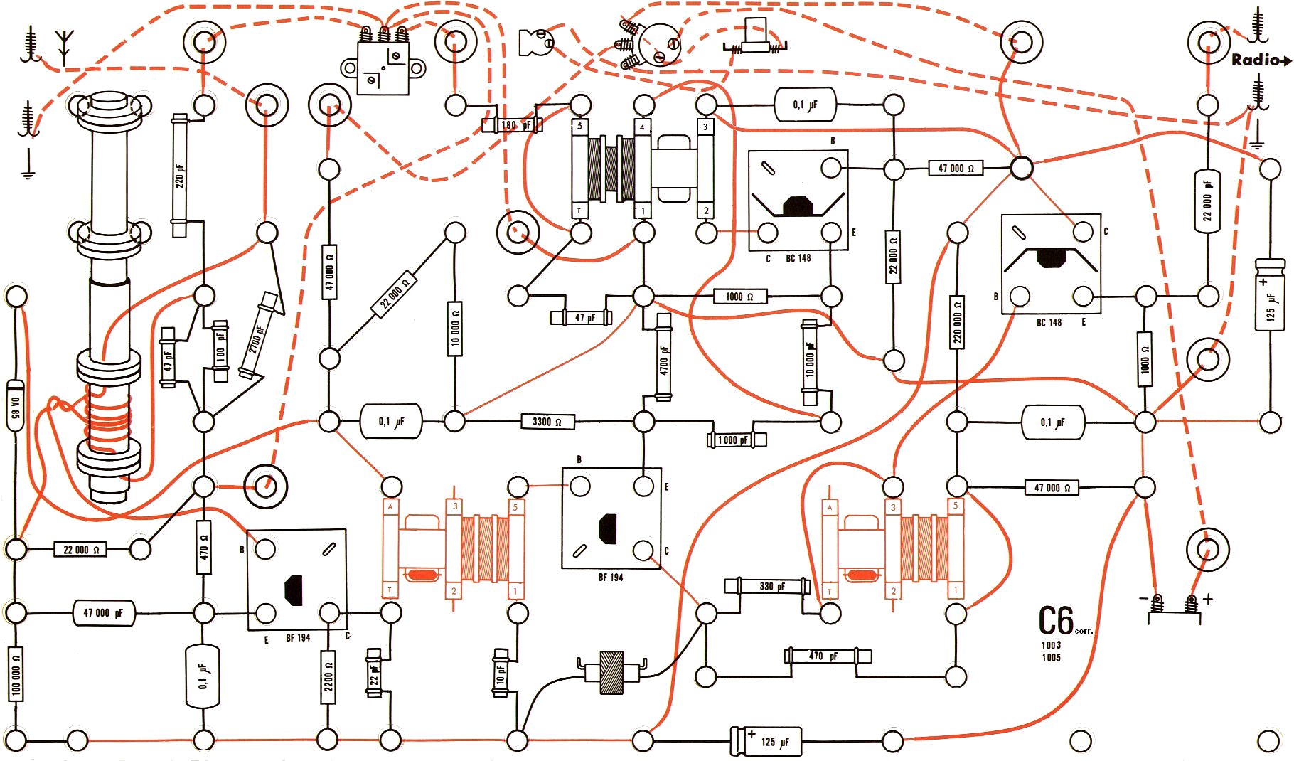
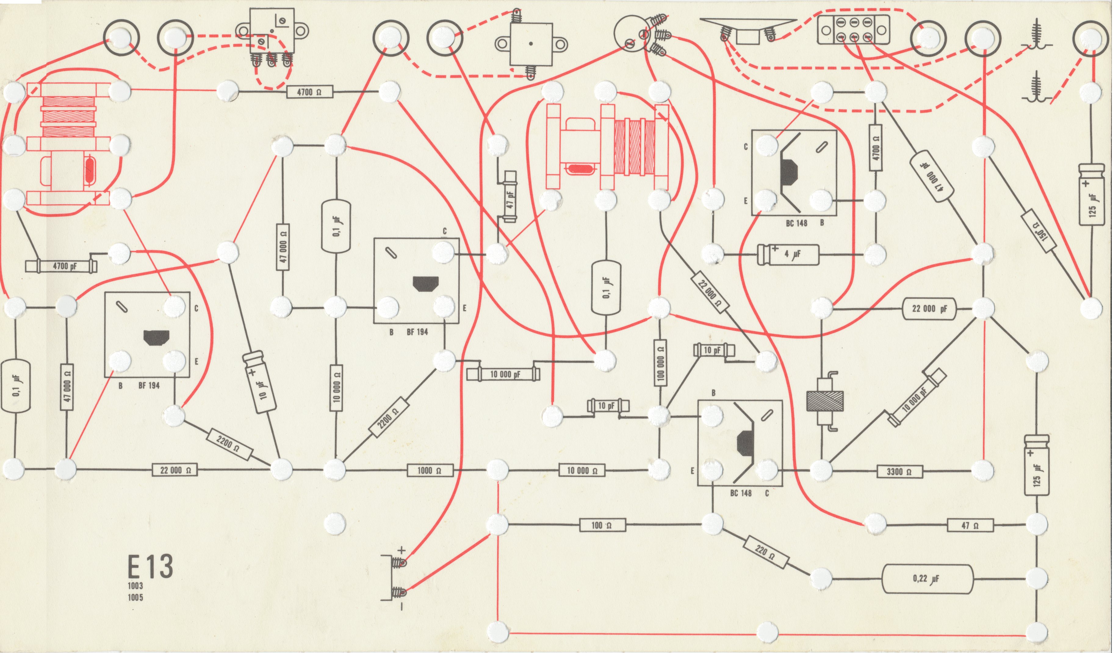
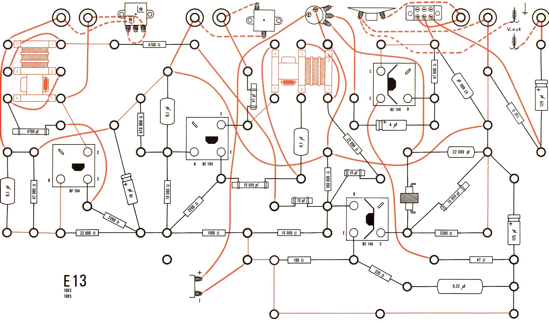
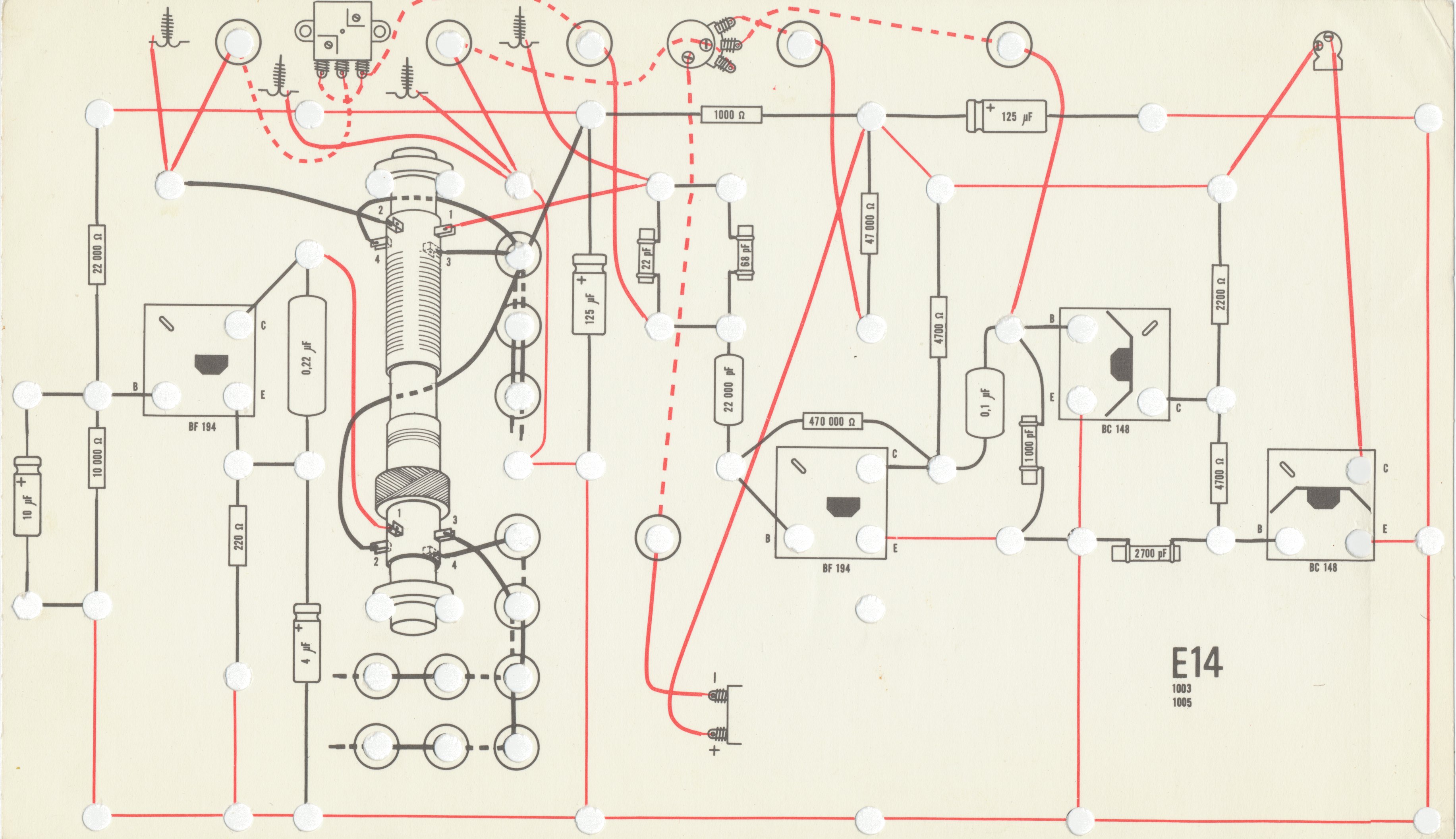
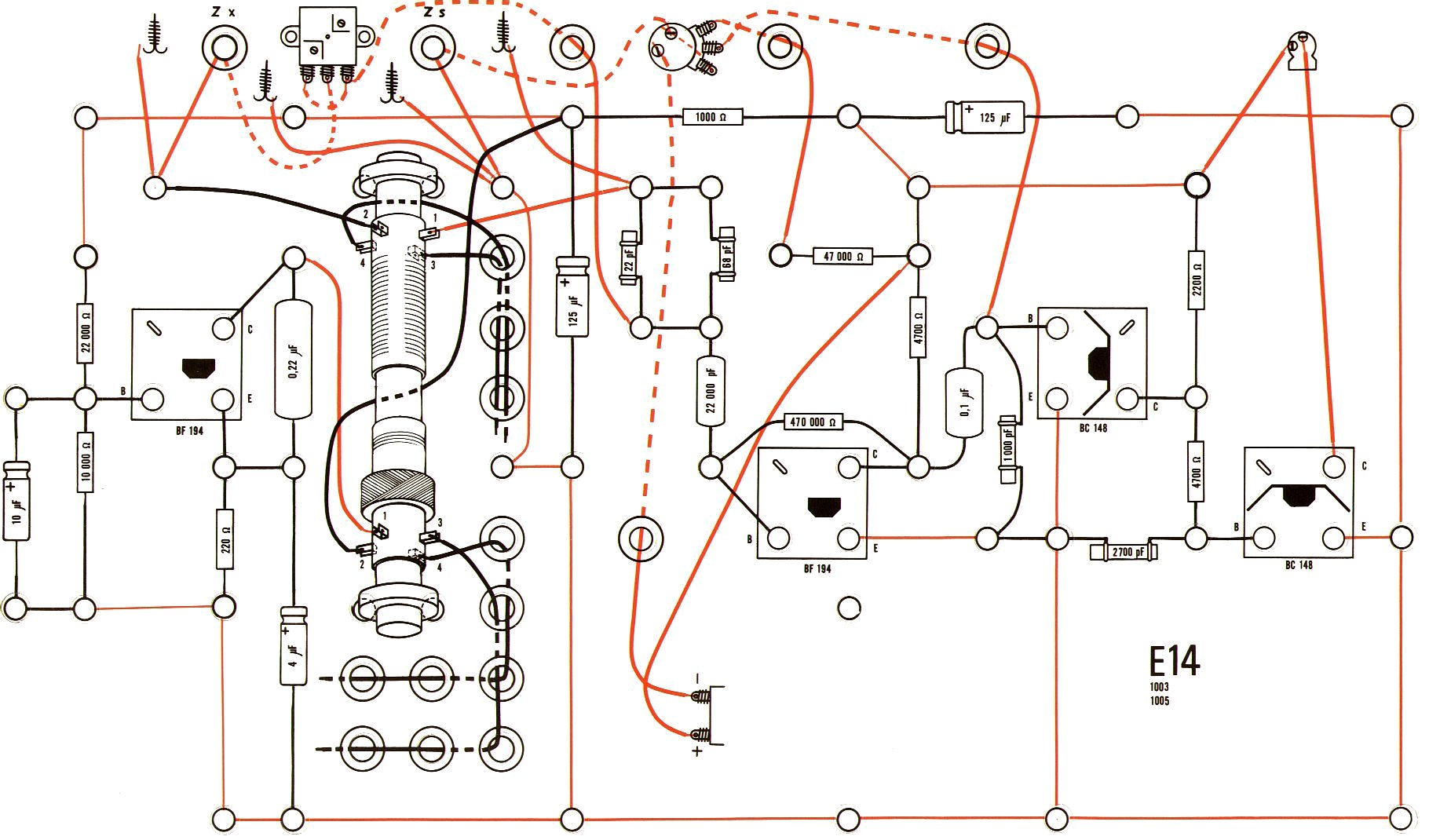
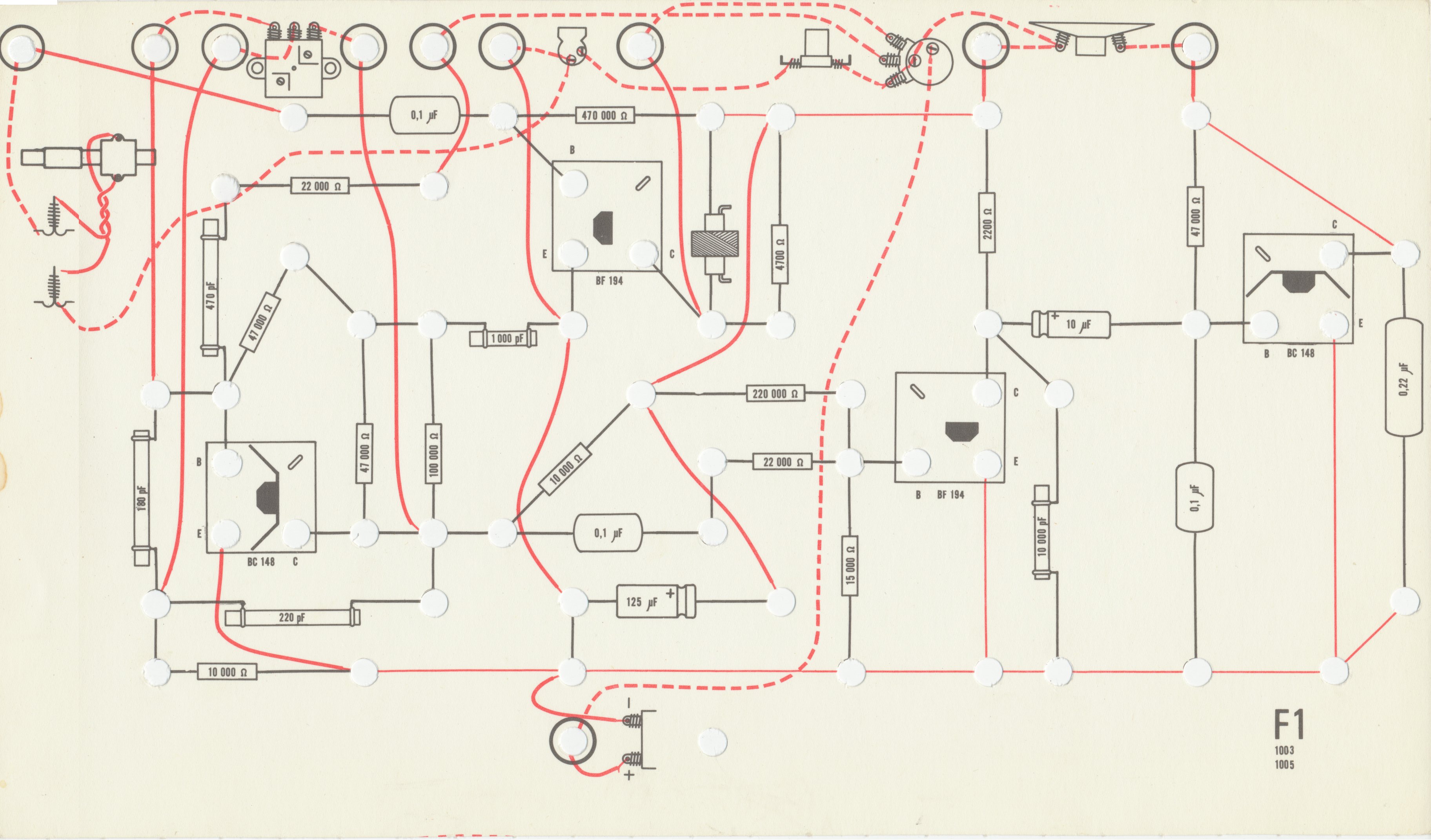
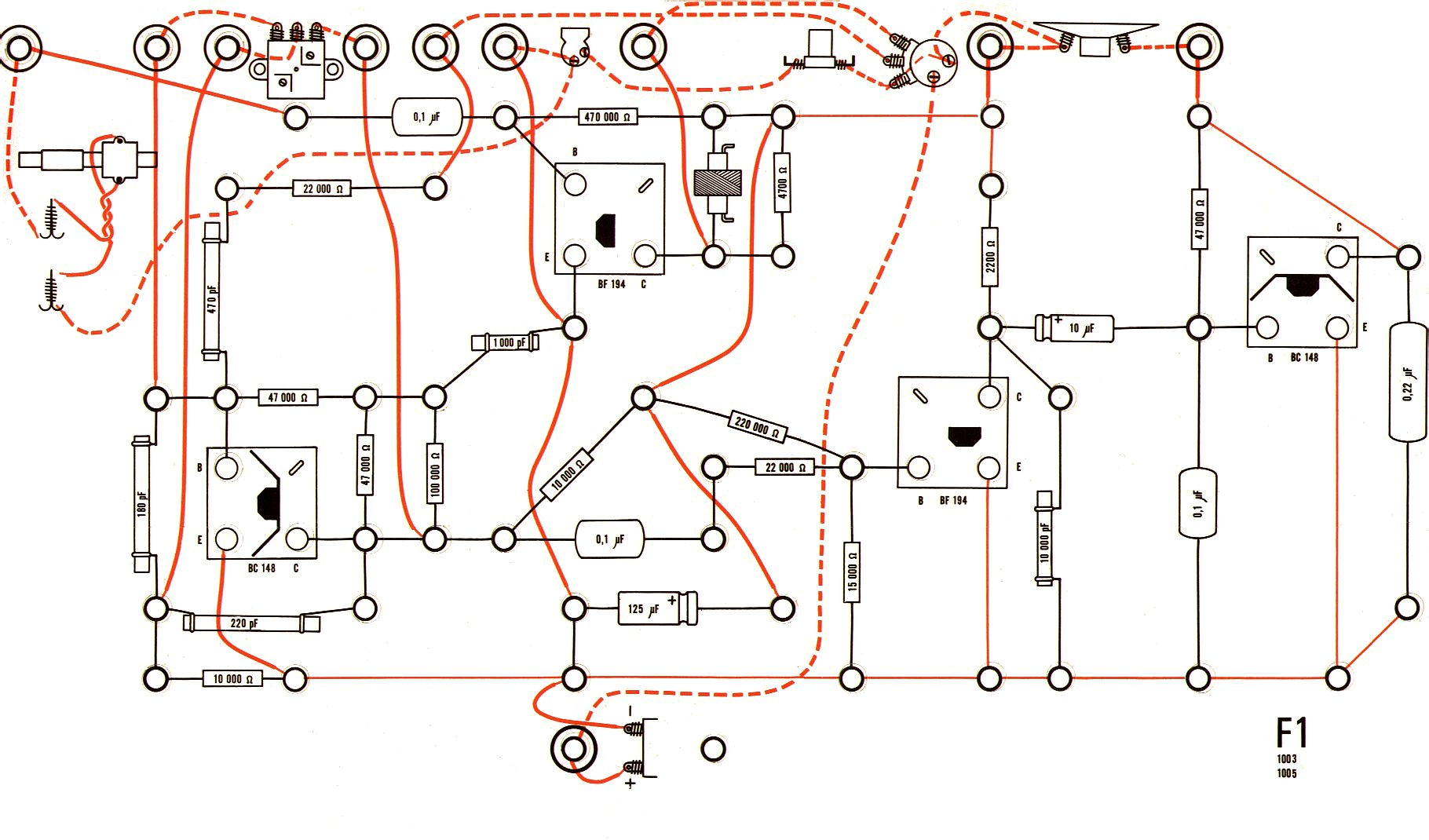
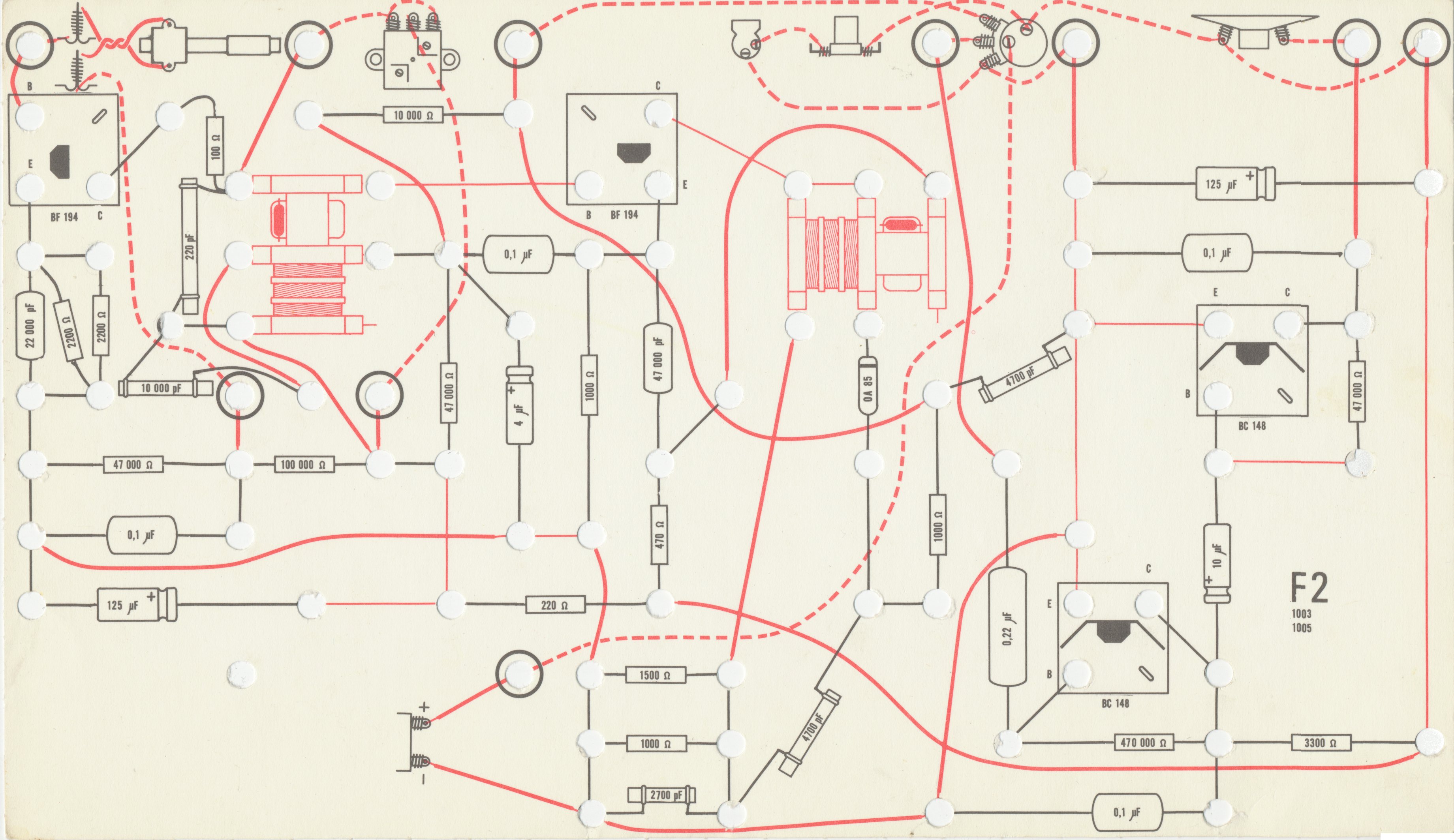
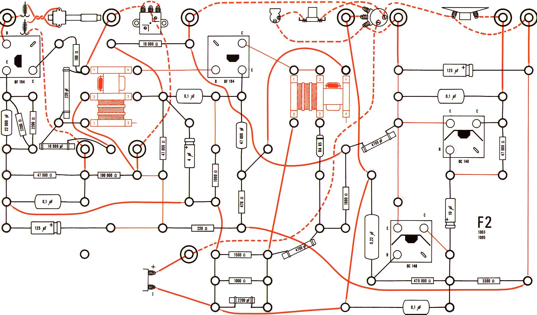
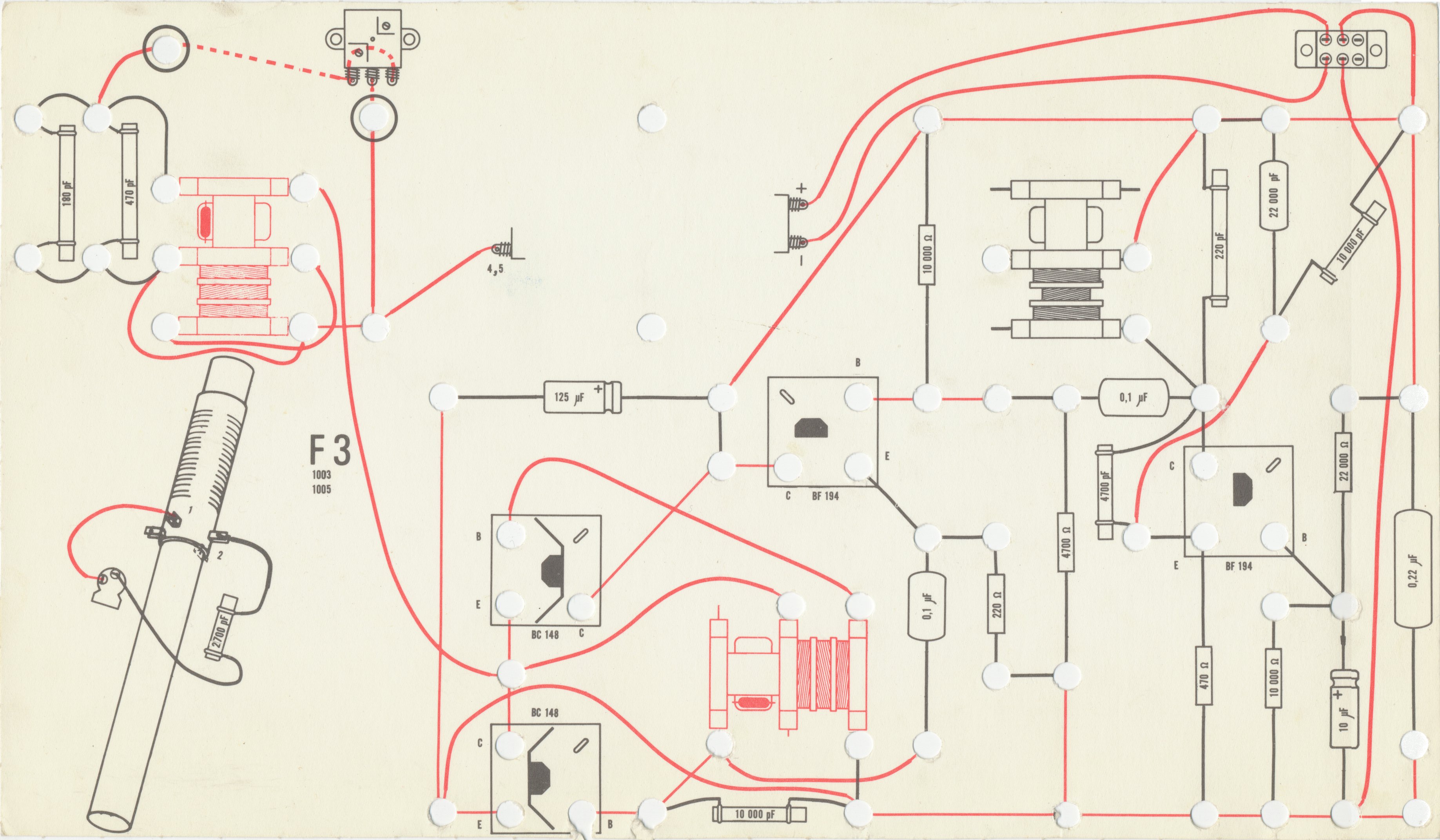
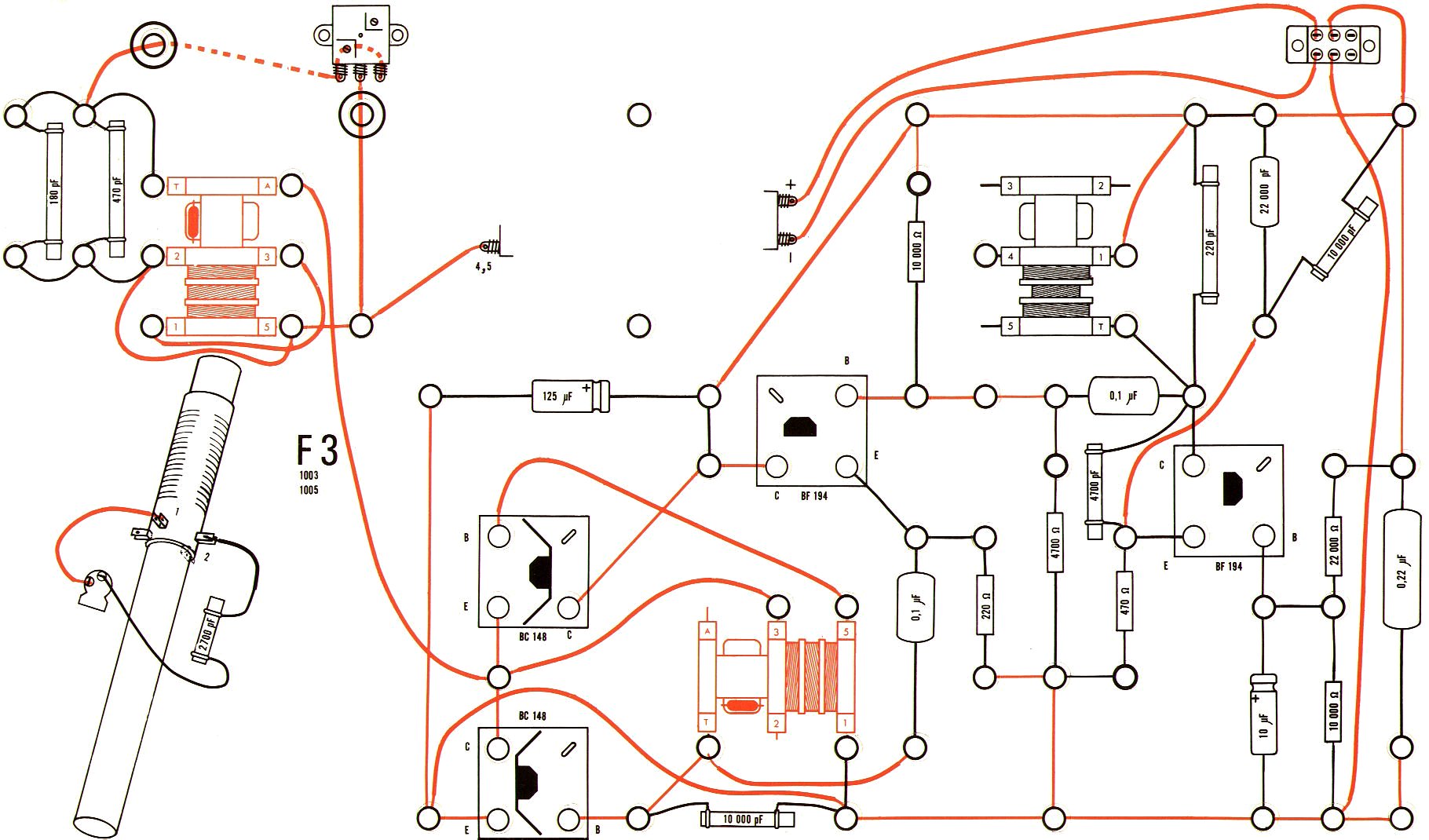
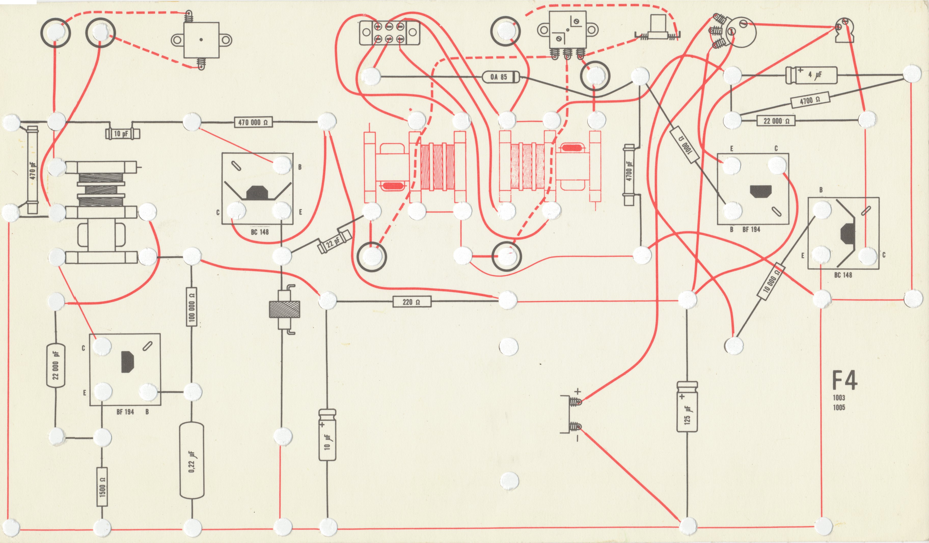
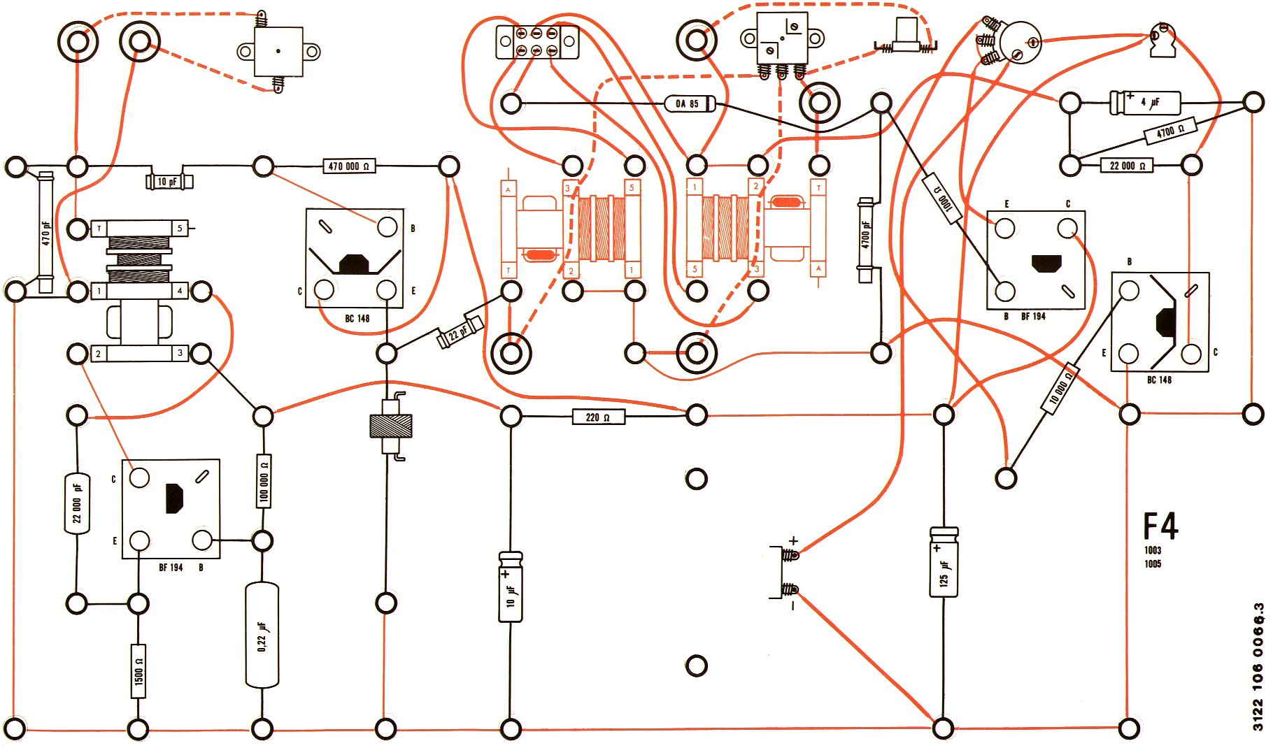
I have scans of two different versions of the diagrams for this kit, one unnumbered and one marked as version 3. There are five categories of differences:
If the set without a version number is version 1 as seems most likely, it is not certain which of these were also present in version 2. My guess based on the dating of the presumed version 1 set is that version 2 was created specifically to include the added resistors. I find it unlikely that it introduced the errors, as one would then expect them to be corrected in version 3. Those errors were in turn most likely introduced with the movement of springs and wires, which would then not have been present in version 2. The front panel terminal connection icons could have been added in either of the two revisions.
| Version 1 or possibly 2 (from a kit with the 1968 version of the manual). |
Version 3 | ||
|---|---|---|---|
|
|
||
|
|
||
| C4 Note the introduction of a 10 Ω resistor in version 3 | |||
|
|
||
| C5 Note the introduction of a 10 Ω resistor in version 3 | |||
|
|
||
| C6 In version 3, an insulated wire has one end misplaced, but this has been corrected here, and the text “corr.” has been added. | |||
|
|
||
| E13 In version 3, one of the two 47 000 Ω resistors is mislabeled 470 000 Ω. | |||
|
|
||
|
|
||
|
|
||
| F2 In version 3, an insulated wire has one end misplaced. | |||
|
|
||
|
|
||